Biomedical Engineering Reference
In-Depth Information
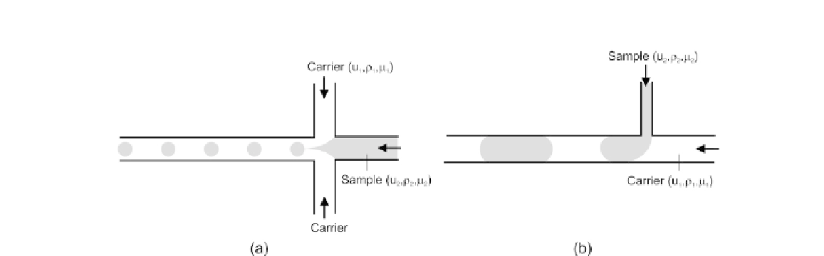
FIGURE 6.27
Two basic configurations for droplet formation: (a) flow-focusing configuration and (b) T-configuration.
Figure 6.27
shows the two basic configurations for passive droplet formation using pressure-driven
flows. The flow-focusing configuration uses the immiscible carrier fluid as sheath flows. By
approximately balancing the Laplace pressure with the shear force, the diameter of the formed droplet
can be predicted as
[40]
:
f
s
D
m
c
g
;
(6.15)
where
s
is the interfacial tension between the two immiscible faces,
m
c
is the dynamic viscosity of the
carrier phase, and
u
/
W
, where
u
is the average
velocity at the gap between the channel wall and the droplet and
W
is the width of the inlet channel
(
Fig. 6.28
).
Alternatively, droplets can be formed with the T-configuration.
Figure 6.29
depicts a simple model
of the formation process of a liquid droplet in another immiscible carrier fluid at a T-junction. Based on
a simple model, the relation between the droplet diameter and other parameters can be revised. The
model assumes a fixed flow rate ratio between the aqueous liquid and carrier liquid (
a ¼ Q
d
/
Q
c
). For
small droplet sizes, the flow rate of the carrier is significant and dominant (
a
1). Furthermore, mass-
related forces, such as inertial force, momentum force, and buoyancy force, are neglected due to the
dominance of surface-related forces, such as drag force and interfacial tension force. For simplifica-
tion, the injection channel and the carrier channel are both assumed to be cylindrical in order to have
the diameters as the single geometric parameters of the microchannels.
For Ca
g
is the shear rate. The shear rate is estimated as
g f
Ca
cr
, the droplet formation process is determined by the balance between the shear force
of the carrier flow and the interfacial tension force at the injection port:
F
drag
¼ F
interfacial tension
1
2
C
D
ru
c
A
D
¼ C
S
p
>
D
i
s
(6.16)
where
r
c
,
U
c
,
A
D
,
D
i
, and
s
are the density of the carrier fluid, the average velocity of the carrier flow,
the effective drag surface, the diameter of the injection port, and the interfacial tension, respectively.
In addition,
C
D
and
C
S
are the drag coefficient and the coefficient for the interfacial tension. The


Search WWH ::

Custom Search