Biomedical Engineering Reference
In-Depth Information
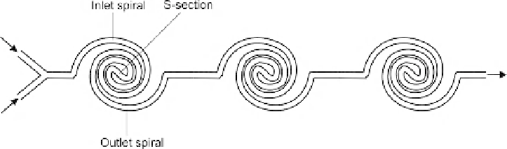
FIGURE 6.13
Micromixer based on spiral microchannel (after
[20]
).
increase of the Dean number. Each mixing unit consists of an inlet section and an outlet section. The
two sections are connected by an S-shaped channel (
Fig. 6.13
). The spiral microchannel was designed
by reducing the radius of curvature by 80% for every 90
turn. In this way, the radius of curvature can
be reduced from the outermost arc to the innermost arc by about 10 times. Unlike a 90
turn (Section
6.2.1), Dean vortices in a spiral microchannel sustain along the flow path. The long channel path of the
spiral microchannel also provides a sufficient residence time for the mixing fluids. Thus, the design
allows mixing at low Reynolds number due to molecular diffusion. While in a straight mixing channel,
the dominant convection at high Reynolds number prevents transversal transport, Dean vortices and
the resulting chaotic advection reduce the mixing length. Thus, this mixer design utilizes both
molecular diffusion and chaotic advection for working under a wide range of Reynolds numbers. The
micromixer reported in
[20]
was fabricated using a simple prototyping technique. The master mold
was etched in the copper layer of a printed circuit board. The mixer was made of a thermoplastic
elastomer by hot embossing. The microchannels are sealed by thermal direct bonding of the molded
part to a cover made of the same material.
Many sequential lamination micromixers have complex three-dimensional structures. Thus,
splitting and recombination of the mixing streams can lead to chaotic advection at low Reynolds
numbers. Such a mixer design was reported by Simonnet et al.
[21]
(
Fig. 6.14
). The side channels are
not used to return the mixing fluids but to split and rejoin it later at the exit of the mixing unit. The
inlets of the side channels are shallower than the microchannels elsewhere, increasing the hydraulic
resistance and avoiding back flow as in the feedback case. The mixer works with Reynolds number less
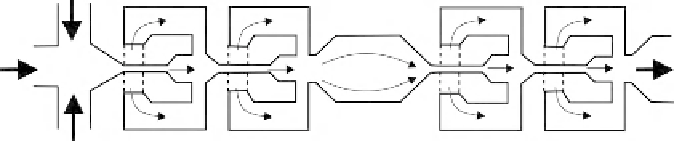
FIGURE 6.14
Planar micromixer design based on splitting and recombination. The dashed lines indicate areas with shallower
channels (after
[21]
).


Search WWH ::

Custom Search