Biomedical Engineering Reference
In-Depth Information
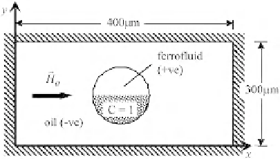
FIGURE 3.33
Schematic of a ferrofluid microdroplet suspended in oil.
where the susceptibilities of ferrofluid and oil are
c
þ
¼
5 and
c
¼
0, respectively. The respective
boundary conditions are
v4
m
vn
;
c
H
o
$
b
n
¼
x
¼
0
;
400
(3.61a)
v4
m
vn
¼
0
;
c
y
¼
0
;
300
:
(3.61b)
Accordingly, the momentum equation has to be modified to include the magnetic force in the
form of Eqn
(3.32)
. For the present two-fluid system, the magnetic force
f
u
can be further reduced
to
[4, 5]
1
2
m
o
jHj
2
f
u
¼
Vc
(3.62a)
where
d
c
d
f
Vf
Vc ¼
(3.62b)
d
c
d
f
¼
ð
1
þ c
þ
Þð
1
þ c
Þðc
þ
c
ÞdðfÞ
(3.62c)
2
½ð
þ c
þ
Þþ
H
ð
þ c
Þ
1
1
Equation
(3.62c)
is derived from Eqn
(3.60)
. In the solution of the fluid transport equations, no-slip
boundary condition is applied at the four walls.
Figure 3.34
shows the magnetic, velocity, and concentration fields generated by the applied
magnetic field. The applied magnetic force stretches the droplet in the direction of the applied field.
Driven by the applied magnetic field, the droplet evolves dynamically to its equilibrium shape where
the magnetic force is balanced by the surface tension force and the velocity field dies down in the
process. Obviously, the droplet has not achieved this equilibrium shape at
t
0.12 s. The twofold
symmetries of the flow field, in this case, help to redistribute species X within the droplet and
enhance mixing.
¼


Search WWH ::

Custom Search