Biomedical Engineering Reference
In-Depth Information
Laser
*
Filter
module
Spectrograph
Catheter
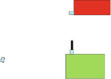
Fig. 1.14
Schematic diagram of the endoscopy Raman system with magnified views of the fiber
tips. The
indicates the location of a 50-m-diameter fiber used to calibrate the spectrometer
(Adapted from Short et al. [
40
], with permission)
an endoscopic Raman probe (including excitation light delivery and Raman signal
collection), a spectrograph, and a CCD detection unit. The design of the endoscopy
Raman system is schematically shown in Fig.
1.14
.
1.3.2.1
Light Source
A wavelength-stabilized diode laser (785 nm, 300 mW, model: BRM-785, B&W
Tek, Newark, DE) was used for Raman excitation. The laser beam was delivered
through a single 200-m core diameter fiber to a filter module, which consisted
of a laser line filter (LL01-785, Semrock, Rochester, NY) and two long-pass filters
(LP02-785RU, Semrock, and RG 715, 5 mm thick, Schott, Elmsford, NY). The laser
beam was collimated through a lens, passed through the laser line filter to reject the
side bands and background fluorescence and Raman signals generated inside the
fiber, and focused into another 200-m fiber for Raman excitation.
1.3.2.2
Endoscopy Raman Probe
The endoscopic probe was a specially designed bifurcated fiber bundle, with one
branch consisting of a single fiber of 200 m in diameter for excitation delivery and
the other branch consisting of 27 fibers of 100 m in diameter for signal delivery.
The 28 fibers were bundled together into a round configuration at the distal end,
approximately 1.8 mm in diameter and 0.75 m long with the excitation fiber in
the center. Another stage of optical filtering was incorporated at the distal end of
the catheter by evaporating interference band-pass filter coatings on the excitation
fiber tip and long-pass filter on the 27 collection fibers. With this configuration of
filters, the fluorescence and Raman background signal from the excitation fiber are


Search WWH ::

Custom Search