Biomedical Engineering Reference
In-Depth Information
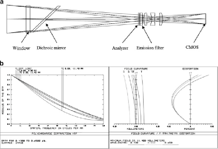
Fig. 9.15
Imaging lens for polarization reflectance and fluorescence imaging. (
a
) Layout and (
b
)
performance plots
works perfectly. Figure
9.15
a shows the layout of this imaging lens; the two positive
singlets on each side are identical. The design also considers the effect of the
polarizer, window, emission, and tilted dichroic filters. The performance of this
imaging lens is plotted in Fig.
9.15
b. It is a well-corrected system with some
remaining spherical aberration, coma, astigmatism, and lateral color. Distortion is
quite small, only 0.02 %, because of the symmetrical configuration.
Figure
9.16
a is the layout of the OCT scan lens. The designed aperture is located
between the two galvo mirrors. MTF in Fig.
9.16
b shows that this lens has a very
good performance with a small amount of spherical aberration. Telecentricity when
the first scan mirror and second scan mirror scan is plotted in Fig.
9.16
c. The largest
chief ray angle is about 1.2 degrees when the first scan mirror scans.
Figure
9.17
shows a diagram of the multimodal imaging system. Inside the box
is the schematic diagram of the OCT imaging system [
55
,
56
]. The light source
is a high-speed frequency-swept external cavity laser (Thorlabs SL1325-P16) with
average output power of 12 mW and 3-dB spectral bandwidth of approximately
100 nm. The light from the laser is split by a 99:1 fiber coupler; 1 % of the light
is coupled to the Mach-Zehnder interferometer (MZI) as the frequency clock of the
laser. The rest of light goes to a fiber-based Michelson interferometer and is further
split to the reference arm and sample arm. In the reference arm, the light from the
Search WWH ::

Custom Search