Biomedical Engineering Reference
In-Depth Information
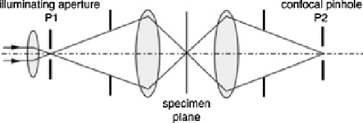
Fig. 6.8
Pinholes in the confocal microscope. P1 is a pinhole spatial filter, P2 is the confocal
pinhole
based mirrors and other scanning systems. Here a brief description of these laser
beam scanners is provided.
Galvanometric scanning is the most widely used scanning technology in
microscopy. This is due to its flexibility and price range. The principle of operation
of a galvanometer is identical to that of a motor in which the magnetic field produced
by an arrangement of permanent magnets is increased or decreased by the field from
a variable current electromagnet. The change in the field makes a magnet or an iron
to rotate. For slow scanning rates of a few frames per second, galvanometer scanning
is sufficient that has rms frequency of about 2 kHz. The scanners consist of a mirror
attached to a shaft that can rotate through a given angular range. Such scanners are
bandwidth limited, and therefore, it is not possible to exactly track an arbitrarily
specified position within the scan range [
12
]. With beam scanning, the light from
the sample must be descanned so that it does not move relative to the pinhole. This
is usually achieved by reflecting a second time from the galvo-mirror.
For video rate imaging, faster scanning of mirrors is required that can be
achieved by resonant scanners [
13
]. The main difference of a resonant scanner to
a galvanometer scanner is that the only moving part in the resonant scanner is a
single-turn coil, which reduces the damping in the scanning system and allows it
to be able to vibrate at very high frequencies, close to its mechanical resonance.
Since these scanners are designed to work close to resonant frequency, their angular
displacement can be very large. There are 10-kHz resonant scanners capable of 60 ˚
scan angles. Resonant scanners also cannot provide random access of points within
their scanning range. They are able to produce a sinusoidal scanning pattern at
frequencies as high as 12 kHz. In such scanners, in order to take advantage of the full
sinusoidal scan, data must be acquired in both the forward and backward directions.
In a polygonal scanning mirror system, very high frame rates can be obtained
[
14
,
15
]. In this scheme, the geometrical centre of a multifaceted polygonal mirror
is attached to a fast rotating shaft. As the motor rotates, the facets of the mirror will
scan the laser beam in a linear pattern. For slow scanning polygonal mirrors, ball
bearings are used in order to keep the price reasonable. At high rotation speeds
or larger mirrors, some problems might arise with precision bearings, such as
lubrication and vibration. Polygon mirrors can be noisy and produce air currents.
Search WWH ::

Custom Search