Biomedical Engineering Reference
In-Depth Information
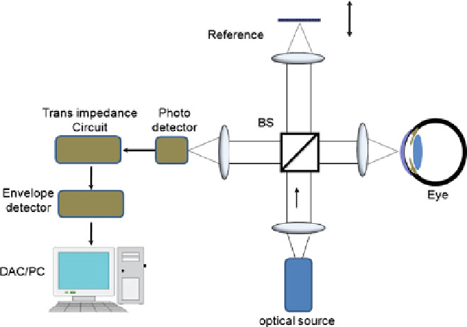
Fig. 5.3
Schematic of a typical first-generation free-space optics-based optical coherence tomog-
raphy setup with balanced heterodyne detection scheme
corresponding to the interference signal is amplified and converted into a voltage
signal by a transimpedance circuit. The amplified signal is demodulated by using
sophisticated electronic envelope detection stages (e.g., lock in amplifier). Then
the demodulated signal is fed into a data acquisition system that is interfaced with
the computer. The data acquisition system is an integral part of the OCT setups
that do all the timing and synchronization between different modular units of an
OCT system. In OCT, the depth information can also be derived from frequency-
domain measurement by taking the Fourier transform of the output spectrum of the
interferogram; this alternative modality has better speed and sensitivity advantages
than conventional time-domain detection scheme, which will be described later in
this chapter.
In general, an OCT system can be considered from a modular viewpoint in terms
of various integrated hardware and software functionalities such as imaging engine,
low-coherence light source, beam delivery and probes, computer control, and image
processing. Figure
5.4
shows the schematic of various modular components of
a generic OCT system. Depending on the specific application, there are many
variant embodiments of the interferometer and imaging engines for wide range of
applications such as polarization-sensitive imaging, Doppler flow imaging, optical
microangiography, spectroscopy, frequency scanning, spectral radar, and parallel
detection.
Search WWH ::

Custom Search