Biomedical Engineering Reference
In-Depth Information
a
b
E
V
G
E
C
G
E
F1
E
F1
-
eV
D
E
F1
C
D
height of the
potential at the
top of the barrier
U
top
k
C
S
V
D
top of the
barrier
E
F1
-
eV
D
V
S
x
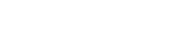
Fig. 2.7
(
a
) Energy map for the ballistic HEMT in the Datta-Lundstrom model and (
b
) the Datta-
Lundstrom equivalent circuit
In this model, the maximum potential energy value between source and drain is
U
top
D
eŒ.C
G
V
G
=C
tot
/
C
.C
D
V
D
=C
tot
/
C
.C
S
V
S
=C
tot
/
C
e
2
n
mob
=C
tot
; (2.16)
where C
tot
D
C
G
C
C
S
C
C
D
and C
G
C
S
;C
D
. The density of mobile charges
in the channel, n
mob
, is calculated by filling with electrons the
C
k and
k states in
conformity with the source and drain Fermi energies, respectively, starting from the
bottom of the conduction band at U
top
, assumed known. U
top
is computed iteratively
by increasing the density of mobile charges until convergence is reached, and I
D
is estimated from the known electron populations in the two halves of the energy
dispersion curve above U
top
.
Nevertheless, contrary to common expectations, the mobility of ballistic carriers
in short-channel HEMTs, is much lower than in long-channel HEMTs (
Shur 2002
).
The effective mobility can be written as
1=
eff
D
1=
ball
C
1=
0
;
(2.17)
where
0
denotes the mobility in the long-channel regime, in which collisions dom-
inate, and
ball
is the mobility associated to ballistic carriers. In the nondegenerate
case, the ballistic mobility has the expression
ball
D
2eL=m
v
th
, whereas in
the degenerate case, the thermal velocity
v
th
D
.8E
th
=m/
1=2
in this relation, with
E
th
D
k
B
T , must be replaced with the Fermi velocity
v
F
.From(
2.17
), it follows that
the mobility decreases significantly when the gate length decreases, in agreement
with experiments; for instance, in GaAs, the mobility is 10;000 cm
2
=Vs for a gate
length of 10m and only 3;000 cm
2
=Vs for a gate length of 150 nm.
For low drain voltage values, the expression of the drain current can be
simplified as
I
D
D
Wq
i
.0/
ball
V
D
=L;
(2.18)
where q
i
.0/ denotes the electron distribution at the source. On the contrary, for high
drain voltages, we obtain


Search WWH ::

Custom Search