Biomedical Engineering Reference
In-Depth Information
a
b
v
v
_
+
∇
p
E
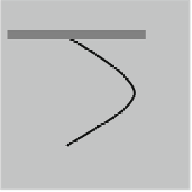
Fig. 1.53
Typical (
a
) microfluidics and (
b
) nanofluidics flow mechanisms
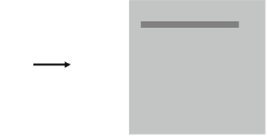
source
reservoir
drain
reservoir
gate metal
electrode
SiO
2
/Si
Fig. 1.54
The nanofluidics transistor
channels where, due to pressure difference, the velocity distribution has a parabolic
shape (Poiseuille flow).
The velocity of the electroosmosis flow profile beyond the Debye length is
given by
v
D
"
0
"
r
E
s
=;
(1.53)
where
s
is the potential at the surface and E is the applied electric field in the flow
direction. Formula (
1.53
) reveals the constant velocity profile for electroosmotic
flow.
The Debye length l
D
decreases when the ion concentration n
i
increases, l
D
/
n
1=
i
, and ranges from 1 to 100 nm for aqueous solutions. In microchannels, the
Debye length is much smaller than the channel dimensions, so that the solution is
isolated from the surface charge and is neutral. On the contrary, in nanochannels
with a dimension smaller than the Debye length, the electrostatic field penetrates
through the channel and thus controls the flow via the field effect. This effect is
analogue to the effect of the gate on a FET transistor, and the devices with 1D
nanochannels analogous to FET channels and working on the above principle are
termed nanofluidic transistors (
Karnik et al. 2005
)(seeFig.
1.54
). In the case of
nanofluidics channels, the ion concentration is modulated by an electrostatic gate.


Search WWH ::

Custom Search