Biomedical Engineering Reference
In-Depth Information
was of 1 V. The asymmetry between the first two cases indicates that the dipole
is closer to the cytoplasmic side of the membrane, the electrical characteristics
indicating that both the nanoelectrical and the biological systems maintain their
properties/functionalities and interact with one another. A true bionanoelectronic
device was created.
In devices that use the whole cell behavior as opposed to the cell membrane
patches referred to above, it is important to be able to introduce electrodes into
cells without destroying them or inducing cell death (apoptosis). Such chip-based
nanoscale electrodes consisting of a metallic post with a hydrophobic band have
been fabricated (
Verma and Melosh 2010
). These electrodes can penetrate into
the cell membrane of red blood cells and form tight seals, with a resistance
of almost 4 G. The stealth probe spontaneously fuses with the cell membrane
because the 5-10-nm-wide hydrophobic band formed by self-assembly mimics the
behavior of transmembrane proteins in the hydrophobic membrane core so that
a bioinorganic lateral junction forms, accompanied by an impermeable gigaohm
seal. Such Pt-tipped stealth probes with hydrophobic bands fabricated onto wider
Ni bottom electrodes with a width of 10m by electron-beam lithography induce
membrane fusion, provide low-resistance electrical access to the tip for injection of
redox-induced current in cells, and insulate the electrodes placed outside the cell.
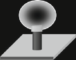
A stealth probe is illustrated in Fig.
9.5
.
A quite common biomolecule in nanoelectronics is DNA. DNA field-effect
transistors (FETs) with source and drain electrodes consisting of metallic mul-
tiwalled CNTs having a diameter of 50 nm have been reported in
Sasaki et al.
(
2006
). A schematic configuration of this DNA-FET is illustrated in Fig.
9.6
.The
CNTs make contact with 15/65 nm Ti/Au pads separated by 7-8m, and the DNA
cell
cell
membrane
hydrophobic
band
post
Fig. 9.5
Penetration of a
stealth probe into a
biological cell
wider
electrode
a
b
CNT
I
Ti/Au
Ti/Au
DNA
V
insulator
gate
Fig. 9.6
(
a
) DNA-based FET with CNT electrodes and (
b
) a typical current-voltage characteristic


Search WWH ::

Custom Search