Biomedical Engineering Reference
In-Depth Information
(A) Incorrect
(B) Correct
Stagnant material
Fuel depth
Slope angle
of skirt
Conveyor
Conveyor
Belt
Minimum
length
Minimum
width
Discharge angle of skirt
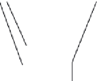
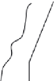
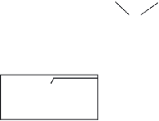
FIGURE 12.9
Two designs of feed chutes between a hopper and a belt conveyor. The design
of (A) is simpler but causes partial flow while (B) gives complete flow.
the chute's downstream section. The chute's expanded and lifted opening
helps the solids spread well, allowing uniform withdrawal. For this reason,
the modified design of
Figure 12.9B
shows the skirt on the chute to be lifted
and expanded (in plan view) to facilitate uniform solid discharge from the
hopper. These angles (slope and discharge) should be in the range of 3
5
.
Figure 12.10
is another illustration of this phenomenon, this time with a
rotary feeder. Here, the design of
Figure 12.10A
is without the short vertical
section like that of
Figure 12.10B
. Solids are compressed in the direction of
rotation and pushed up through the hopper. The design on the right uses a
short vertical chute that limits this backflow only to the chute height, giving
a relatively steady flow.
The two key requirements for chute design are: (1) the entire cross sec-
tion of the outlet must be active, permitting the flow of solids; and (2) the
maximum discharge rate of the chute must be higher than the maximum han-
dling rate of the feeder to which it is connected.
A restricted outlet, caused by a partially open slide gate, results in funnel
flow with a small active flow channel regardless of hopper design. A rectan-
gular outlet ensures that feeder capacity increases in the direction of the
flow. With a belt feeder, the increase in capacity is achieved by a tapered


Search WWH ::

Custom Search