Biomedical Engineering Reference
In-Depth Information
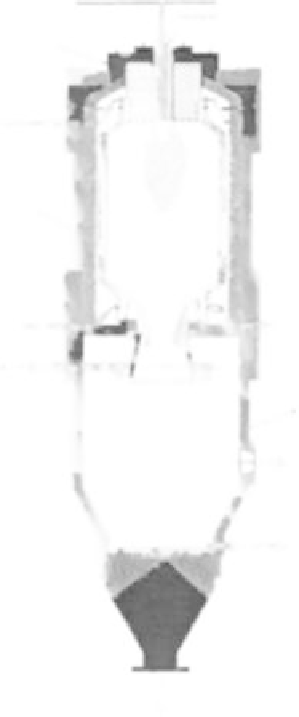
Gas to pilot burner
Fuel
Oxygen
Burner
Pressure
water outlet
Cooling screen
Pressure
water inlet
Quench
water
Cooling jacket
Gas outlet
Water
overflow
Granulated slag
FIGURE 8.16
A schematic of a top-fed downflow entrained-flow gasifier.
Figure 8.16
, and (ii) the side-fed upflow (used by Koppers-Totzek, the
Shell gasification process, Prenflo, and the Lurgi multipurpose), shown in
Figure 8.17
.
8.4.1 Top-Fed Gasifier
Top-fed gasifiers use a vertically cylindrical reactor vessel into which pul-
verized fuel (biomass or coal) and gasifying agent(s) are conveyed by oxy-
gen and injected from the top. This vessel resembles a vertical furnace with
a downward burner (
Figure 8.16
). The fuel and the gasifying agent(s) are
injected into the reactor through a jet that generally sits at the reactor's mid-
dle section.


Search WWH ::

Custom Search