Biomedical Engineering Reference
In-Depth Information
Upper
zone
T
3
m
2g
,
T
2g
m
Sa
,
T
Sa
m
g
,
T
2
Middle
zone
m
w
,
T
w
m
RME
,
T
RME
T
2
m
1g
,
T
1g
m
Pr
,
T
Pr
m
Pa
,
T
Pa
m
0g
,
T
1
m
b
,
T
0b
T
1
m
0c
,
T
0c
m
Ba
,T
Ba
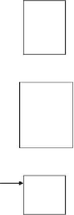
FIGURE 7.10
Model of a CFB gasifier.
Plug flow through the bubble and emulsion phases without mass transfer
between phases.
Plug flow of gas upward in the core and solid backflow in the annulus.
The following sections present the essentials of a model for a CFB com-
bustor and one for a bubbling fluidized-bed gasifier (Kaushal et al., 2008). A
typical one-dimensional steady-state model of a CFB combustor, as shown in
Figure 7.10
, assumes gases as ideal and in the plug-flow regime. The riser is
divided into three hydrodynamic zones: lower dense bed zone, intermediate
middle zone, and top dilute zone. The solids are assumed uniform in size with
no attrition. Char is a homogeneous matrix of carbon, hydrogen, and oxygen.
A bubbling fluidized-bed gasifier is divided into several zones with dif-
ferent hydrodynamic characteristics: dense zone and freeboard zone for bub-
bling beds and core-annulus for circulating beds. The dense zone additionally
deals with the drying and devolatilization of the introduced feed.
Superheated steam is introduced at the lower boundary of the dense zone.
Each zone is further divided into cells, which individually calculate their
local hydrodynamic and thermodynamic state using chosen equations or cor-
relations. The cells are solved sequentially from bottom to top, with the out-
put of each considered the input for the next. The conservation equations for
carbon, bed material, and energy are evaluated not in each cell but across the


Search WWH ::

Custom Search