Cryptography Reference
In-Depth Information
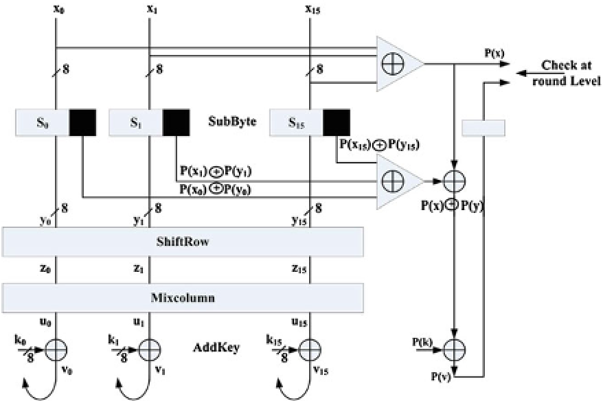
Fig. 6.3
Parity for state [424]
the parity
P
is affected neither by the ShiftRows operation,
which only changes the byte position in the State array, nor by the MixColumns
operations, as demonstrated by Wu et al. [424]. This parity bit is XORed with the
parity of the key
k
,
P
(
y
)
is determined.
P
(
y
)
(
)
, and stored in a one-bit register. Errors are detected when
this predicted parity bit differs from the input parity computed at the beginning of the
next round, which corresponds to the actual parity bit of the preceding round's output.
Implemented on a Xilinx Virtex 1000 FPGA, this solution results in 8 % of hardware
overhead and 5 % of performance degradation. We will refer to this architecture as
“Parity for State”.
Bertoni et al. [34] propose the use of a parity bit that is associated with each byte
of the State matrix of a 128-bit iterated hardware implementation with ROM-based
S-Boxes (see Fig.
6.4
). Predicted parity bits on S-Box outputs are stored as additional
bits in the ROMs (nine bits instead of eight in the original S-Boxes). In order to
detect errors on input parities and in the memory, the authors propose increasing
each ROM to 512
k
9 bits in such a way that all the ROM words addressed with a
wrong input address (i.e. S-Boxes input with a wrong associated parity) deliberately
store values with a wrong output parity so that the detection mechanism will detect
the fault. As before, the parity bit associated with each byte is not affected by the
ShiftRows operation. Conversely to the preceding scheme, where the global parity bit
on the 128 bits remains unchanged after the MixColumns operation, when working
at the byte level, the parity after the MixColumns operation is affected, therefore
requiring the implementation of prediction functions. Finally, the parity bits after the
AddRoundKey operation are computed as before by adding the current parity bits to
×