Biomedical Engineering Reference
In-Depth Information
Figure
6.5.
Schematic of hydraulic pressure and flow in tangential flow filtration.
where P
feed
¼
retentate side inlet pressure, P
permeate
¼
permeate side pressure,
P
retentate
¼
retentate side outlet pressure, Q
R
¼
retentate flow rate, and A
¼
membrane
area.
Wheelwright [20] proposed a simplified mass transfer model based on the hydraulic
resistances of the membrane and the gel layer. For a systemwhere constant viscosity can
be assumed, the governing equation for permeate flux becomes
1
R
g
þR
m
J
filtrate
¼ k
TMP
¼
TMP
where k
¼
mass transfer coefficient, TMP
¼
transmembrane pressure; R
g
¼
gel layer
resistance, and R
m
¼
membrane resistance.
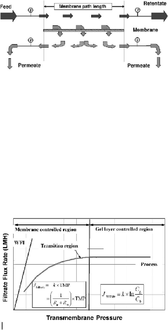
As shown in Fig. 6.6 and described by Ladisch [21], there are three distinct regions
where the transmembrane pressure and the cross-flow rate influence permeate flux to
varying degrees. At lower transmembrane pressures, permeate flux is influenced by both
membrane and gel layer resistances and is proportional to the pressure. In this region,
Figure
6.6.
Effect of transmembrane pressure on permeate flux and the three TFF operating
regions.