Biomedical Engineering Reference
In-Depth Information
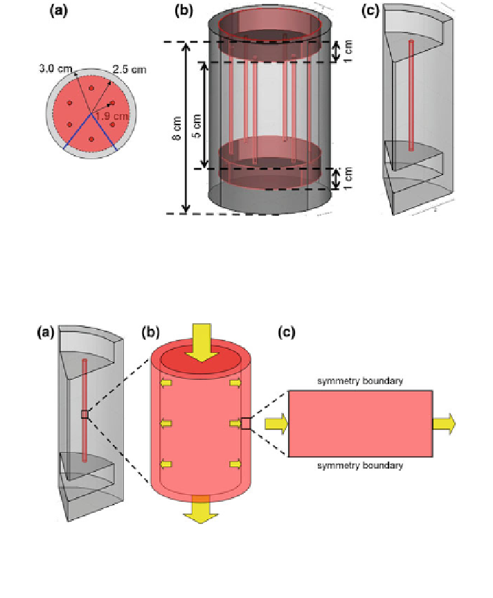
Fig. 7 Schematic of PSF bioreactor geometry used for 3D fluid flow modeling in COMSOL.
a Top view showing dimensions of the chamber, manifold and placement of tissue constructs.
b 3D rendering of entire bioreactor geometry in COMSOL. c Simplified geometry used for
computation based on symmetry
Fig. 8 Schematic of domain used for the DO model in the PSF bioreactor. a The domain from
the flow problem was simplified to the tissue component as shown in b and c. c The diffusion-
convection-reaction problem domain used in COMSOL consisted of a 300 lm thick slab of
tissue with identical DO on both sides
A schematic of the geometrical simplification is provided in Fig.
7
. The upper
manifold was removed from the computational domain and its surface served as a
no-slip wall boundary condition. The upper end of the construct lumen and the
lower manifold central port served as fluid inlets into the system and the outlet was
the annulus around the upper manifold. The vertical fluid plane on either side of
the construct utilized a symmetry boundary condition. Constants used for the flow
model (and subsequent DO model) are provided in Table
1
. The model again
accounted for flow of fluid through the tissue based on Darcy's Law (Eq.
3.1
). The
model equations were solved using an appropriate transient or stationary solver to
Search WWH ::

Custom Search