Biomedical Engineering Reference
In-Depth Information
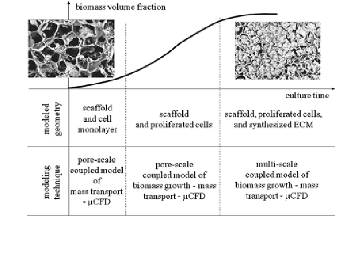
Fig. 4 Hierarchy of computational modelling techniques for cartilage tissue growth, following
the evolution of the geometry of the cell environment upon culture time. A coloured version of
this figure is available on the online version of the topic
3 Coupled Models of Medium Flow and Mass Transport
A rough understanding of transport limitations in porous constructs has been
obtained, in absence of flow, by Botchwey et al. [
2
,
3
] and Sengers et al. [
45
] using
homogeneous models of tissue-engineered constructs. This amounts to solving
Eq. (
1
) with a constant nutrient diffusivity and v = 0 in the entire scaffold domain X,
instead of considering the actual microscopic structure of the domain X
e
with its
associated complex empty and filled substructures. In up-to-date recent tissue
engineering bioreactors, the cell-seeded scaffold is immersed in a medium which is
induced to flow through or around the scaffold surface in a perfusion flow apparatus.
A simple strategy for increasing mass transport to cells would appear to be to increase
the medium flow rate, but high flow rates induce high shear stresses on cells, which
may be harmful instead of beneficial, at least at early stages of tissue growth.
This complexity presents serious hurdles in determining the appropriate values
of flow rate and medium solute concentration. Flow around scaffolds in a con-
centric cylinder bioreactor has been studied by Williams et al. [
49
] by solving
Eq. (
2
) coupled with Eq. (
1
) in the whole bioreactor domain. In this model, the
biomass volume is not accounted for in the geometry, but an equivalent volumetric
consumption rate is used at the right-hand side of Eq. (
1
). Such a model allowed to
compute flow fields, shear stresses and oxygen profiles around the constructs.
Incorporating flow through the scaffold in a direct-perfusion configuration
complicates the situation by establishing a velocity scale which is related to the
Search WWH ::

Custom Search