Biomedical Engineering Reference
In-Depth Information
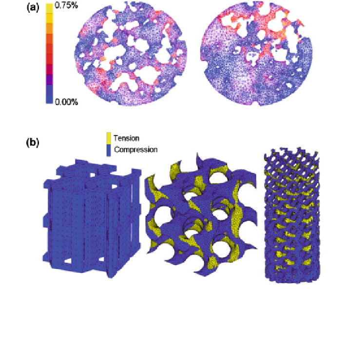
Fig. 3 a Examples of distribution of octahedral shear strain in two samples for CaP cement (left)
and glass (right) scaffold morphologies (modified from Lacroix et al. [
9
]). b Major strain
distribution in RP pores; the zones under tension or compression strain are delimited; prism
hexagonal shape with 70% of porosity (left), gyroid pore structure with 70% of porosity (middle),
and gyroid pore shape distributed gradually through the height of scaffold (global porosity equals
70%) (right) (data from Olivares et al. [
5
])
The mechanical parameters computed in the scaffold surface are considered as
the stimuli or signals felt by the cells attached. Dependent on the stimuli magni-
tude (strain for example), the stimuli will alter cell proliferation or phenotype
differentiation. Generally, for bone tissue engineering applications a compressive
load is applied to determine the strength and the strain distribution in the scaffold
wall surface (see Fig.
3
). The effect of mechanical stimuli was studied through
micro-FE models for macroporous CaP cement and for a porous glass ceramic
scaffold. The octahedral shear strain distribution on a two dimensional section of
both samples is shown in Fig.
3
a; higher strains are found in areas close to the
pores with magnitudes up to 0.75% for the application of a compressive strain of
0.5% [
9
]. The strain distribution throughout the section is quite inhomogeneous
due to the inhomogeneous pore distribution.
Under a compressive load equivalent to a uniaxial strain of 0.5%, the structures
shown in the Fig.
3
b presented a higher proportion of material experiencing
Search WWH ::

Custom Search