Biomedical Engineering Reference
In-Depth Information
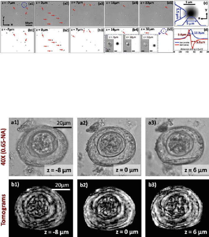
Fig. 4.15
, 0.65-NA) of different depths of a cham-
ber filled with randomly distributed micro-beads (5m diameter). (
b1
-
b5
) Lensfree tomograms
for the corresponding layers are shown to demonstrate depth-sectioning capability. The
solid
arrows
in each image point to the beads that are in focus at a given depth. (
c
) Zoomed tomographic
image through the center of an arbitrary 5m bead. (
d
) The axial line profile (along z) and its
spatial derivative for the same bead as in (
c
). The
inset
enclosed with the
dashed rectangle
(see
b4
-
b5
) shows sectioning of two axially overlapping micro-beads both by lensfree on-chip tomography
and conventional microscopy (40
(
a1
-
a5
) Bright-field microscope images (40
, 0.65-NA)
Fig. 4.16
(
a1
-
a3
) Computed tomograms for different depths of an
H. nana
egg are shown. (
b1
-
b3
) 40
microscope images of the same object provided for comparison purposes
tomograms through the object provide distinct details at different layers, demon-
strating successful optical depth sectioning. We also verified that the thickness
estimated from the tomograms of the egg matches its actual physical thickness of
40m[
20
].
Even though the results presented in this section are shown for small volumes
of interest, the imaging performance is maintained over a large FOV of
20 mm
2
and a depth of field of
1 mm, enabling our tomographic microscope to probe
a large biochip volume of
20 mm
3
with a decent 3D spatial resolution [
20
].
The main reason that our axial resolution is limited to
7m is the fact that we