Biomedical Engineering Reference
In-Depth Information
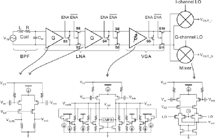
Fig. 8.7
Receiver chain (From Ref. [
3
])
pulse sequence generator also sets the timing scheme for the receiver by controlling
switches S3 through S11 (see also Fig.
8.4
) in the way explained in Sect.
8.2.1
.
8.2.4
Heterodyne Receiver with Passive Amplification
Figure
8.7
shows the detailed structure of the heterodyne receiver, which consists
of a low-noise amplifier (LNA), a variable-gain amplifier (VGA), two mixers, and
switches S3 through S11, whose usage was explained in Sect.
8.2.1
. To handle
the NMR signal-to-noise ratio substantially lowered by the ping-pong-ball-sized
magnet in the palm system or the lossy on-chip coil in the 1-chip system, the noise
figure (NF) of the receiver should be minimized. To this end, both minimization
of the LNA's input-referred noise and optimum LNA-coil noise matching are
necessary.
To minimize the LNA's input-referred noise, we take the following measures
in our new LNA design: (1) resistive loads are used in place of active loads. This
obviates the need for a common-mode feedback circuit, thus reducing the noise
sources. To compensate for the low gain due to the passive loads, we use a two-stage
amplifier; (2) PMOS transistors are used as input devices to minimize 1=f noise and
substrate coupling from digital circuits; and (3) the cascode configuration attenuates
coupling between the local oscillator and the LNA. For the optimum LNA-coil noise