Biomedical Engineering Reference
In-Depth Information
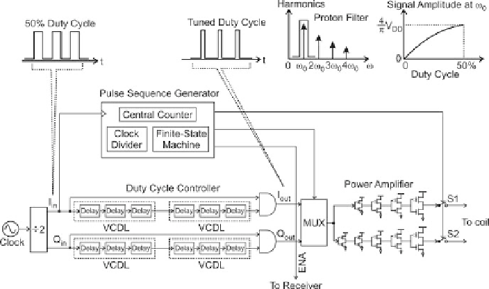
Fig. 8.5
Transmitter chain and power tuning scheme (From Ref. [
3
])
that goes into the protons during the NMR excitation phase. The transmitter in
the 2-kg portable system did not integrate a PA, since meeting the power tuning
requirement was not trivial with an integrated PA. The new transmitter in the
palm and 1-chip systems, which is shown in detail in Fig.
8.5
, integrates the entire
front-end transmitter chain, including a PA. We manage to tune the PA's output
power by exploiting the proton's natural high-Q (
10
4
) filtering ability.
To start with, the PA is realized as a differential chain of cascaded four inverter
stages (Fig.
8.5
, bottom right). The inverters are consecutively quadrupled in size
to sequentially amplify power and ensure drivability at the output. This class-D
arrangement is simple to design and does not consume static power, but it produces
a square wave output with fixed voltage amplitude of the power supply V
DD
, thus,
calling for a technique to tune its output power.
To this end, we tune the duty cycle of the transmitted signal. A given transmitted
square wave (frequency: !
0
; amplitude: V
DD
/ with a specific duty cycle (Fig.
8.5
,
top) assumes a particular power distribution of the fundamental tone at !
0
and
higher-order harmonics. The power distribution over the harmonics varies with the
duty cycle. Here we only need to look at the variation of the power at !
0
with
the duty cycle, for higher-order harmonics lie outside the “proton filter” band:
protons are a high-Q (
10
4
) band-pass filter centered at !
0
, in the sense that they
are not excited by signals that lie outside the frequency band. As the duty cycle
is altered from 0 % to 50 %, the !
0
-component changes its voltage from 0 to
.4=/ V
DD
(Fig.
8.5
, top right). This effectively corresponds to the output power
tuning.