Biomedical Engineering Reference
In-Depth Information
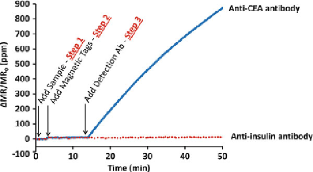
Fig. 7.9
Real-time monitoring of sensors during autoassembly immunoassay. Addition of the
sample and magnetic nanotags contribute negligible signal (upon addition of the magnetic
nanotags, there is a very small signal rise due to detection of magnetic nanotags in solution
above the sensor). However, once the detection antibody is introduced, the magnetic nanotags are
clearly measurable on sensors functionalized with the appropriate capture antibody and antigen.
The negative control sensors, coated with anti-insulin antibody, remain flat, indicating negligible
nonspecific binding. The y-axis units are the change in magnetoresistance normalized to the initial
magnetoresistance presented in parts per million (ppm)
per sample, it is wasteful and underutilized to have on the order of 100 sensors
per nanosensor array investigate only five biomarkers. It would be more efficient
if the high-density sensor array could be subdivided where several patient samples
could be run simultaneously on a single chip using parallel microfluidic channels.
In addition, with cross-reactive antibodies, reagents can be separated into their own
reaction chambers when implementing microfluidic integration in order to minimize
this phenomenon. Further, the use of microfluidics can be optimal for handling
biological samples when only very small sample volumes are available. Fortunately,
microfluidic chip integration is highly compatible with magnetic nanosensor arrays
(Fig.
7.10
). In this very basic microfluidic chip, each microfluidic channel contains
eight sensors for up to 8-plex protein detection on any given sample in any given
channel. This will yield eightfold more tests per hour and amortize the chip cost
over multiple samples.
The microfluidic chips are fabricated using standard soft lithography techniques.
Polydimethylsiloxane (PDMS) is cast onto an SU8-based mold. The PDMS is then
cured and peeled from the mold. The thickness of the mold is used to form the
fluidic channels. External connections are then punched into the inlets and outlets
of the PDMS blocks. The final microfluidic chip design is comprised of 200
m-
wide channels that are each 20m high and the channel pitch is 400m. For more
details on microfluidic biosensors, please refer to Chap.
2
.