Biomedical Engineering Reference
In-Depth Information
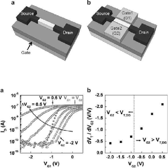
Fig. 5.15
Schematics of (
a
) a conventional nanowire FET and (
b
) a double gate nanowire FET
Fig. 5.16
(
a
) I
D
V
G1
for various V
G2
conditions and (
b
) impact of the change in V
G2
on the
change in the threshold voltage (Copyright 2010 American Chemical Society)
There are two ways to drive the FET in the double-gate structure: the single-gate
(SG) mode and the tied double-gate (DG) mode [
43
]. In the SG mode, G1 is used as
a drive gate, and G2 is used as a supplementary gate to pin the channel potential at
a fixed voltage. In contrast, in the DG mode, G1 and G2 are electrically connected,
which implies that the same voltage is always applied to G1 and G2; that is, it has a
symmetrical bias (V
G1
D
V
G2
/.
The data measured in the SG mode (hollow circles) in Fig.
5.16
a show that
the drain current by G1 can be modulated according to the bias condition of G2.
The increment of the G2 voltage (V
G2
/ from a negative to positive value tends to
lower the V
T
value and degrade the subthreshold slope (SS), which is defined as
d.V
G1
/=d.
log
I
D
/; that is, it becomes less steep. However, the characteristics of the
DG mode (filled squares) show a steeper SS than that of the SG mode due to the
greater control over current in the double - gate FET [
43
].
AsshowninFig.
5.16
b, when V
G2
is larger than V
T;
DG
(V
T
in the DG mode), V
T
changes significantly in response to small changes in V
G2
: However, changes in V
T
are less sensitive to V
G2
when V
G2
is lower than V
T;
DG
. Thus, the sensitivity in terms
of V
T
is less affected by the condition of V
G2
.