Biomedical Engineering Reference
In-Depth Information
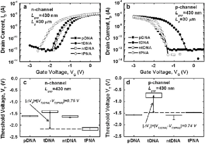
Fig. 5.11
Transfer characteristics (I
D
-V
G
/ of (
a
) an n-channel and (
b
) a p-channel DMFET for a
targeted workgroup and various control groups. Statistical variation of V
T
shifts for target DNA,
noncomplementary target DNA, and target PNA hybridizations in (
c
) an n-channel and (
d
)ap-
channel DMFET (Copyright 2011 IOP Publishing Ltd)
the type of FET. The target biomolecules were also replaced with DNA, which is a
negatively charged biomolecule. PNA, which has no electrical charge, was used for
control experiments to verify the dielectric constant effect.
Figure
5.11
shows the transfer I
D
V
G
characteristics and statistical variation
of V
T
according to the biomolecule binding steps for the n-channel and the
p-channel DMFETs. In the graphs, the charge effect and the dielectric constant
effect counteract each other in the n-channel DMFET, whereas they are acting in
the same direction to shift V
T
in the p-channel DMFET. With these data, it was
verified that the dielectric constant increment and negative charges in DNA were
competing against each other in the n-channel DMFET, as shown in Table
5.1
.The
V
T
value of the p-channel DMFET shifted toward the positive side either after
target DNA (analyte) or target PNA (analyte) hybridization, whereas the V
T
value
of the n-channel DMFET shifted to the positive side only when the target DNA
was hybridized. In addition, it shifted to the negative side when the target PNA was
hybridized to probe DNA (receptor). A notable result was that the differences in
the V
T
shift between the PNA hybridization and DNA hybridization to the probe
DNA had the same value, indicating that the differences were entirely caused by the
negative charges in the DNA. From this result, it was confirmed that an increment
in the sensing margin is possible via the proper selection of the FET type, that is,
n- or p-channel, according to the charge polarity of the analyte.