Biomedical Engineering Reference
In-Depth Information
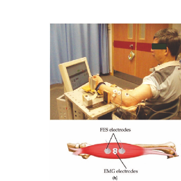
Figure 8.1
The FES-robot training experimental setup (a). The configuration of the FES
electrodes and EMG electrodes on a muscle (b).
3
0
-3
8
10
12
14
16
18
20
22
24
3
Stimulation
Artifact
2
M Wa ve
Volun tar y EMG
1
0
-1
9.83
9.84
9.85
9.86
9.87
9.88
9.89
9.9
9.91
9.92
9.93
t s
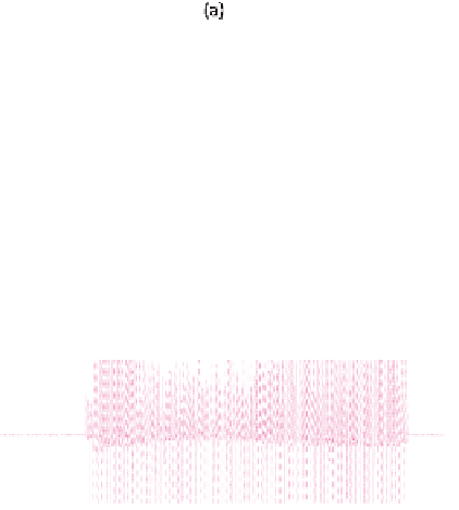
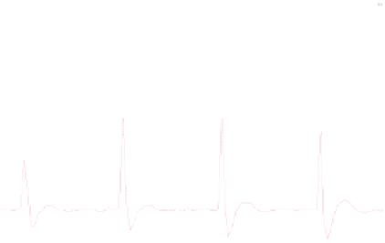
Figure 8.3
The captured EMG signals after the process of sample-and-hold. The upper
panel shows the EMG signal before (dotted line) and after (solid line) the process of sample-
and-hold. The lower panel shows the enlarged signals in the upper panel.