Biomedical Engineering Reference
In-Depth Information
11.4 ISOKINETIC EXERCISE
11.4.1 Control Method
This system relies on the brake alone to control the angular velocity, ensuring
high safety. The rotation velocity is controlled by commands given based on
appropriate brake torque determined with the handle rotation torque operated by
users. Such passive velocity control was used by Kikuchi
et al
. (Kikuchi, 2003) for
an ER fluid brake.
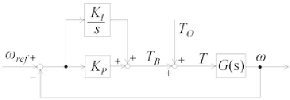
This paper describes a proportional-integral (PI) velocity control, as shown in
Fig. 11.8
,
and applied using the MR fluid brake. Symbols are defined in
Table 11.1
.
In control, operation torque given in training by the user is dealt with as
disturbance. Only with the brake, the system cannot output torque in the same
direction as that of rotation. Therefore, reference torque, either zero or negative,
must be made zero when a positive value is commanded.
Control input
ω
re f
is arbitrarily set in a range from zero to the maximum
speed the user develops. Control input remains constant from control start to end.
Handle operation is started whenever the user likes. Brake control begins when
handle rotation speed exceeds set value
ω
re f
. The integrator remain set at zero
until handle rotation speed exceeds set value
ω
re f
.
Figure 11.8
Block diagram for velocity control of MR Fluid Brake.
Table 11.1
Definitions of each parameter for
velocity controller
ω
re f
:
Reference angular velocity [rad/s]
ω
: Angular velocity [rad/s]
T
B
:
Reference torque [Nm]
T
O
: Operation torque (disturbance) [Nm]
T
:
Torque [ ]
K
P
:
Proportional gain [Nms/rad]
K
I
:
Integral gain [Nm/rad]