Biomedical Engineering Reference
In-Depth Information
set surfaces representing the interfaces with the minority phase
(so-called “skeletal surfaces”). The cross-sectional representations
of this structure, defined by projections along the desired lattice
vectors, are computed by the intersection of the surfaces with the
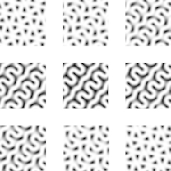
desired plane. Figure 2.17 shows simulated sections normal to the
(211) lattice vector taken at different heights through the unit cell.
This face has the “double-wave” pattern characteristic of the gyroid
structure. The series in effect views thin slices through the unit cell
at various distances along the (211) lattice vector.
z=0.00
z=0.05
z=0.10
(a)
(c)
z=0.15
z=0.20
z=0.25
(b)
z=30
z=35
z=0.40
[001]
[010]
[100]
×
2)
standard cubic unit cell of the gyroid structure with the minority phases
removed. (b) A section perpendicular to the (211) lattice vector shows the
characteristic “double wave” pattern. The (11
Figure 2.17
Simulated section views of (211) lattice planes. (a) A (2
1) direction runs parallel
to the waves. (c) simulated cross sections with the matrix phase bright
and voids left by removal of the minority phase black. Each section has a
thickness of 5% of the repeat distance along (211) and is taken at a height
(as a fraction of the total lattice vector). Images (a) and (b) are reproduced
with permission from Ref. [65].
z
2.4.6.2 Replicaion of gyroid network arrays
Figure 2.18a,b shows SEM micrographs in both surface and cross-
sectional projections of a porous template made from a gyroid-
forming PFS-
-PLA copolymer with the PLA network phase
removed at RT after thermal annealing at 180
b
°
C. The (211) lattice


Search WWH ::

Custom Search