Environmental Engineering Reference
In-Depth Information
Morris (HR Wallingford 2003) provides a com-
prehensive examination of embankment perfor-
mance with analysis of significant, historical
embankment failures. HR Wallingford's Perfor-
manceandReliabilitystudy (HRWallingford2004)
on flood defence assets draws upon this work,
amongst others, and includes a number of perfor-
mance models relating to embankments.
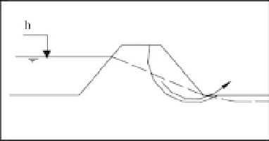
Fig. 6.3
Piping through an earth embankment (HR
Wallingford 2004).
Piping
Failure modes
There are a number of potential failure mechan-
isms for earth embankments. Some cannot be
uniquely identified using visual inspection as they
require geotechnical, and destructive, testing.
Examples of failuremodes for earth embankments
are given below. A list of failure modes for em-
bankments and other asset types is provided in the
full report (Long et al. 2006)
Piping can occur through or underneath an em-
bankment structure (Fig. 6.3). Piping underneath
an embankment is uncommon in the UK due to
the nature of the soil types. Piping is caused by
excessive seepage through an embankment lead-
ing to the washout of fill material. This can even-
tually lead to the formation of a pathway through
or under the structure. Once this has been created,
catastrophic failure can occur rapidly, often
referred to as a
blowout
. Piping can be very hard
to identify prior to imminent failure.
In terms of visual inspection for the occurrence
of piping there are factors that should be assessed.
The soil type making up the embankment is the
dominant factor. Any asset or area prone to piping
failures will need to be investigated closely.
Indicators of piping would range from actual
springs of water appearing in the embankment
(probably near the outer toe) to signs of saturation
or pooling of water around the outer slope. The
presence of animal burrows within an embank-
ment could reduce the effective embankment
width and provide an easy pathway for piping to
occur.
Slope instability
Slope instability covers a range of failures identi-
fied from a number of sources such as shallow
slips, deep rotational failures or sliding of sections
of the slope (Fig. 6.2). The exact nature and cause of
instability are hard to assess through visual in-
spection. Due to this, these various geotechnical
processes have been grouped into this failuremode
for the purposes of condition indexing.
In terms of the visual assessment of slope in-
stability there are a number of signs of its occur-
rence, such as cracking, fissuring, movement of
slope sections, slipping of slope and slumping or
heaving of slope sections.
Overtopping leading to breach
The overtopping of an embankment is not a failure
in itself. The embankment is designed to hold
back water up to the height of its crest and then
be overtopped. However, if the overtopping is of
sufficient force and duration it can lead to erosion
of the crest and outer slope (Fig. 6.4). Significant
erosion of the crest will reduce the standard of
protection of the embankment and increase the
likelihood of
Fig. 6.2
An example of slope instability in an earth
embankment (HR Wallingford 2004).
further overtopping. Significant