Geoscience Reference
In-Depth Information
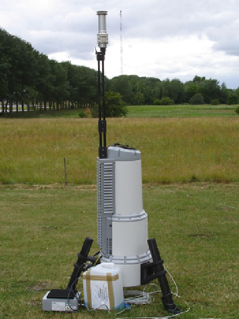
Fig. 3.13
Beam-focussing
Doppler wind LIDAR. The
laser beam is sent and
received through the slanted
top of the grey upper part of
the main instrument. The
small mast to the left carries
the wind direction sensor
The compactness of these new LIDAR systems also opens the potential to mea-
sure horizontally oncoming gusts upstream of a wind turbine at hub height. This
capability was first successfully demonstrated in a proof-of-principle experiment in
2003, in which a beam-focussing LIDAR was mounted on the nacelle of a Nordex
N90 turbine (Harris et al.
2006
). Due to the high data rate of 10 Hz, the short inter-
ruptions of the beam by the blades of the turbine did not impede the measurement.
A wind speed of 15 m s
−
1
and a focusing of the beam at 150 m distance permits a
warning time of 10 seconds in order to adapt the turbine. With 25 m s
−
1
wind speed
the warning time is 6 s, still considerably longer than the timescale for blade pitch
adjustment. More research is needed to quantify the benefit of incorporating LIDAR
as part of the turbine control system; such a scheme might involve staring directly
upwind, but it could also employ a scan pattern in order to probe a wider area in
front of the blades. A similar LIDAR system has also been installed in a rearward-
looking configuration on a test turbine by Risø (Bingöl
2005
); a programmable
scanner permits examination of turbine wake behaviour in space and time.
3.5.4.3 Optical Coherence Tomography for Range Determination
In addition to signal delay and beam focusing, further attempts have been made
to enhance the range resolution of optical remote sensing. One approach is to
Search WWH ::

Custom Search