Geoscience Reference
In-Depth Information
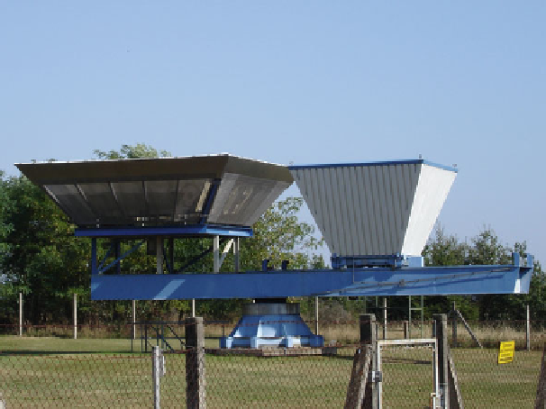
Fig. 3.2
Boundary layer wind profiler of the German Weather Service at the Richard Aßmann
observatory in Lindenberg. The electromagnetic antenna is to the
left
, the acoustic sound source to
the
right
differ by 90
◦
. The half-power beam width is of the order of 8
◦
(Caccia et al.
2004
).
Like RADAR instruments the emitted beams from windprofiles have side lobes,
which can lead to the recording of fixed echoes. Wind speed measurements from
these instruments are disturbed by moving obstacles (swaying trees, wind energy
converters). Shielding to the sides can reduce the disturbance by fixed echoes.
3.2.2 Micro Rain RADAR
Micro rain RADARs are also based on the RADAR technology. They are frequency-
modulated continuous-wave (FM-CW) RADAR instruments, which emit a verti-
cally directed beam with a wavelength of 1.25 cm (24.1 GHz). Micro rain RADARs
record not only the backscattered intensity (reflectivity) but also analyse via the
Doppler shift of the backscattered signal the falling velocity of the scattering pre-
cipitation particles. With this coinciding information on fall speed and drop size, a
quantitative precipitation measurement is possible (Peters et al.
2002
,
2005
). The
instrument has an emitting power of 50 mW and can resolve 28 height range inter-
vals between 35 and 200 m. If a height interval of 100 m is chosen, a layer from 300
m to 3000 m above ground can be analysed. The minimum time resolution is 10 s;
typically 60 s is used. The small instrument which weighs just 12 kg operates with
a parabolic antenna of 60 cm diameter that emits the 2
◦
wide beam. The device is
usually mounted on a mast of a few metres height and does not require a radome
(Fig.
3.3
).
Search WWH ::

Custom Search