Information Technology Reference
In-Depth Information
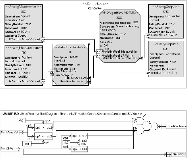
Fig. 7.
UML AP control structure diagram of a control solution for controlling the process
Fig. 8.
An illustration of the first interlocking solution
The detailed logic of the first interlocking solution is presented in figure 8. The so-
lution is designed to activate the brake outside the intended working area if the speed
request is driving the cart away from the working area. In order to be able to revert back
to the working area, the brake is not activated if the speed request is towards the allowed
working area. In order to work well, the system should probably also wait for the cart
to stop before deactivating the brake; however, because of simplicity this feature was
not modelled.
After specification of the detailed control solution, the transformation, discussed in
section 4, was used to transform the UML AP control solution to ModelicaML and
to append it to the existing model of the physical process (see figure 6). In order to
simulate the model, the ModelicaML model was further transformed to Modelica code
with OpenModelica tooling. The shifting from UML AP model of the control solution
to simulateable model of the system including both the process and the control system
was, thus, automated with two model transformations.
The simulation result related to the first interlocking approach is presented in figure
10a. At the beginning, both the position and velocity of the cart are 0. The speed request
(from the operator) is ramped from 0 to 1 and kept at 1 for 7 seconds in order to drive
Search WWH ::

Custom Search