Information Technology Reference
In-Depth Information
Fig. 18 shows the response of the wind generator with different rotor inertia to a
three phase fault created at the middle of 400kV line. The effect of inertia can be
noticed in the speed of the generator. The generators with larger inertia are more
stable in case of fault compared to the generator with smaller inertia. The first swing
in rotor speed for 50kgm
2
is 1.28pu, 1.26pu for 100kgm
2
, 1.24pu for 150kgm
2
and
1.22pu for 200kgm
2
. No distinct differences in the response of the active power,
electrical torque and the terminal voltage are seen.
1.35
0
1.3
-0.2
1.25
-0.4
1.2
-0.6
1.15
-0.8
0
1
2
3
0
1
2
3
(
b) Time (s)
(
a
) Time (s)
51.5
20
51
15
50.5
10
50
5
49.5
0
49
0
1
2
3
0
1
2
3
(
c
) Time (s)
(d) Tim
e
(s)
0%
30%
70%
100%
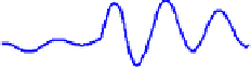
Fig. 17.
Response of (a) DFIG speed (b) DFIG active power (c) PCC frequency and (d) PCC
voltage to 3 phase fault (200ms duration) at different locations on the 20kV line
0.2
1.3
0
1.25
-0.2
1.2
-0.4
1.15
-0.6
1.1
-0.8
0
0.5
1
1.5
2
2.5
3
0
0.5
1
1.5
2
2.5
3
(a) Time (s)
(b) Time (s)
0.8
0.8
0.6
0.6
0.4
0.4
0.2
0.2
0
0
-0.2
0
0.5
1
1.5
2
2.5
3
0
0.5
1
1.5
2
2.5
3
(c) Time (s)
(d) Time (s)
150Kgm
2
200kgm
2
0%
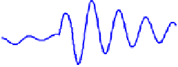
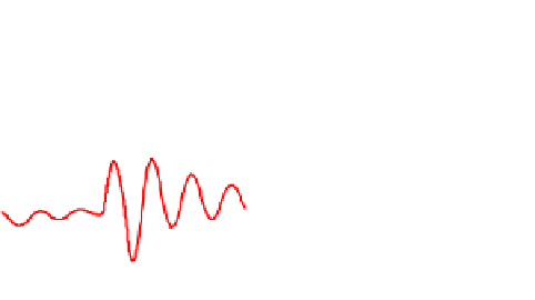
Fig. 18.
Wind farm with DFIG of different inertia


Search WWH ::

Custom Search