Information Technology Reference
In-Depth Information
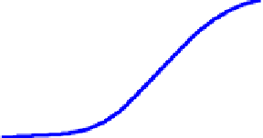
Fig 4 depicts the maximum power tracking of a variable speed wind turbine at
different wind speed.
(Pitc
h
angle beta = 0
deg)
14.4 m/s
1.2
13.2 m/s
1
0.8
12 m/s
0.6
10.8 m/s
0.4
9.6 m/s
0.2
8.4 m/s
6 m/
s
7.2 m/s
0
0
0.5
1
Turbine Speed (pu)
Fig. 4.
Maximum torque tracking of a variable speed wind turbine
2.3
The Mechanical Shaft System Model
Adequate model of the mechanical drive train is required when the study involves the
response of a system to heavy disturbances. It is better to represent the shaft by at
least two- mass model [12] as show in Fig 5 where the turbine is coupled to the
generator through a gearbox.
θ
1
θ
2
Fig. 5.
Two mass model of the mechanical shaft system
From the figure, the following equations can be derived (10)-(17)
d
d
ω
2
H
t
=−
T
Ts
(10)
t
m
1
d
d
ω
2
Hg
r
=−
Ts
T
(11)
2
e
Where,
2
J
ω
J
ω
2
g
H
=
and
H
=
T
(12)
g
T
2
2
2
nP
2
nP
pg
g


Search WWH ::

Custom Search