Information Technology Reference
In-Depth Information
During the architecture analysis, system synthesis by assigning functions to identi-
fied physical architecture elements (subsystems, components) is carried out (Fig. 6).
Finally we create a kinematic joint diagram (Fig. 7) with connectors regarding to
application points and with links representing the field or the type of joints between
two elements.
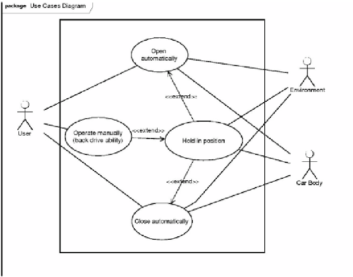
Fig. 4.
Use cases diagram of the power lift gate system
3.2
Vector-Based Mechanical Modelling Derived from System Topology
The previous SysML diagrams bring to light the key parameters and the topology of
the power lift gate system. In order to optimize these key parameters, this mechanical
problem has to be translated into equations. We propose to use a highly suitable me-
thod [5] for multi-domain systems such as automotive mechatronic components.
Based on a topological analysis of the system, this generic method delivers equations
that can be processed by a solver. It relies on the works of Kron [6], Branin [7] and
Björke [8]. Here, our method is restrained to the mechanical study of the static equili-
brium of the lift gate but it may also be used to express the internal structure of the
electric cylinder (screw and nut system, tubes, gearbox, spring, sensors, electrical
engine and electronic components...).
The isolated system includes the lift gate with the electric cylinder between the
points M and N, the car body being an external system. Let us assume that: the me-
chanical joints are perfect; points A, M and G belong to the system boundary; there is


Search WWH ::

Custom Search