Biology Reference
In-Depth Information
Objective
lens
Pinhole
Emission filter
APD
Dichroic mirror
Chan 1
G (
t
)
Chan 2
t
Time
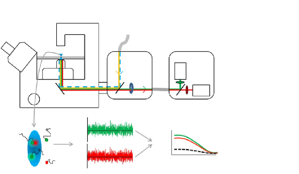
FIGURE 11.1
FCCS setup. Light from a pulsed 440 nm diode and a continuous 514 nm Ar
þ
laser are
focused into the sample using highly corrected objective lens with a large numerical aperture.
A line is scanned perpendicular to the membrane at millisecond intervals. The fluorescence is
guided via a pinhole into the detection unit where a dichroic mirror and emission filters
separate the light into two sensitive detectors. Diffusion of monomeric and dimeric fluorescent
receptors through the detection volumes causes intensity fluctuations over time that can be
analyzed by fitting the auto- and/or cross-correlation curves.
through a silicone oil immersion 60
UPlanSApo objective (NA 1.3) into the sam-
ple. Although not discussed in this chapter, total internal reflection fluorescence
(TIRF) combined with FCS could be useful for measuring membrane receptors as
well, since TIRF will only excite molecules within a region of a few hundred nano-
meters above the cover glass, thereby reducing the size of the observation volume
and background contributions from the cell cytoplasm (
Hassler et al., 2005
). A crit-
ical part of the equipment is the objective lens, especially since multicolor analysis is
being used here. To minimize detection of volume shape distortions within the cells,
a silicone immersion objective with high numerical aperture (N.A.) is used, which
approaches the refractive index of the cellular environment closely, resulting in
high-quality intracellular FCS curves (
Hink, 2012
).
Cellular samples grown on round coverslips are stored in Attofluor sample
holders. The emission light is guided via a size-adjustable pinhole, set at 120
m,
through the Olympus detection box to the fiber output channel. The optical fiber
is coupled to a custom-made detection box (PicoQuant) containing PDM avalanche
m