Graphics Reference
In-Depth Information
(a)
(b)
(c)
(d)
(e)
(f)
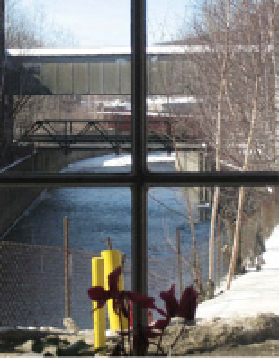
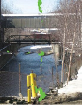
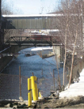
Figure 3.22.
Results of patch-based inpainting. (a) The original image. (b) The inpainting mask.
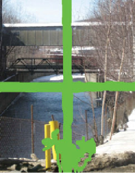
(c) The final inpainted image. The bottom row illustrates the result after (d) 200, (e) 800, and
(f) 2,000 iterations. Note that strong linear structures are propagated through the inpainting
region first.
Figure
3.22
illustrates an example result showing several intermediate steps; we can
see that the algorithm tends to propagate strong linear structures through the target
region first, leaving large flat regions until the end. While the result has several regions
that look unusual (e.g., along the left crossbar and on the foreground post), several
regions are very convincing (e.g., the bridges, trees, and foreground terrain). PDE-
based inpainting cannot achieve a result with this level of realistic texture.
Drori et al. [
126
] proposed a similar inpainting method at about the same
time, which used a coarse-to-fine approach and Laplacian-pyramid-based blend-
ing instead of direct copying of pixel regions. They also allowed the target patches
to adaptively change size and the source patches to change in scale and orientation,
permitting a wider range of possibilities at the cost of speed.
Sun et al. [
481
] noted that while patch-basedmethods try to continue strong linear
features into the target region, these methods cannot guarantee that salient features
like straight lines or junctions will correctly “meet up” in its interior. They proposed a
belief-propagation-based algorithm to first complete salient structures drawn in the
target region by the user, afterward filling in the remaining pixels with a patch-based