Graphics Reference
In-Depth Information
also assume we have a binary mask
M
specifying the desired boundary, so that pixels
inside
S
have
M
0, and compute a Gaussian pyramid
G
for this mask. Then we compute a Laplacian pyramid
=
1 and pixels inside
T
have
M
=
L
I
{
}
for the composite image
as follows:
L
i
(
L
i
(
L
i
x
,
y
)
=
G
i
(
x
,
y
)
x
,
y
)
+
(
1
−
G
i
(
x
,
y
))
(
x
,
y
)
,
i
=
0,
...
,
N
(3.6)
We sum the Laplacian components according to Equation (
3.5
) to get the new image.
Effectively, the transition region is wider at lower spatial frequencies and narrower
at high spatial frequencies, producing a more natural transition between the source
and target. Figure
3.5
illustrates the process for the same images as in Figure
3.3
; note
the higher quality of the composite and the relative lack of artifacts.
The general approach of a multiresolution filter-bank decomposition applies to
other operators besides the Laplacian. For example, a
steerable pyramid
[
453
] fur-
ther decomposes each bandpass image into the sum of orientation bands, which
can be used to selectively enhance or de-emphasize components at different ori-
entations. Another important alternative is a
discrete wavelet transform
(e.g.,
[
277
,
278
]), which also represents images at different scales and canbe computed very
efficiently.
(a)
(b)
(g)
(c)
(d)
(e)
(f)
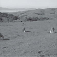
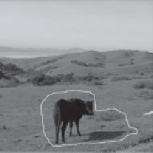
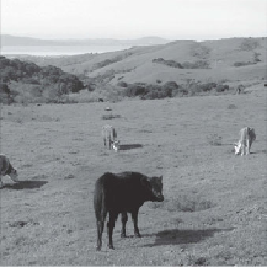
Figure 3.5.
Laplacian Image Compositing. (a) The target image. (b) The source image, indicating
the boundary of the compositing region. (c) Several levels of the Laplacian pyramid for the target
image. (d) Several levels of the Laplacian pyramid for the source image. (e) Several levels of the
Gaussian pyramid for the compositing mask. (f) The combination of the source and target at each
level according to Equation (
3.6
). (g) The final composite.