Graphics Reference
In-Depth Information
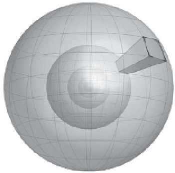
n(p)
Figure 8.31.
The spherical bins used to create a 3D
shape context.
p
Registered
RGB image
LiDAR
scanner
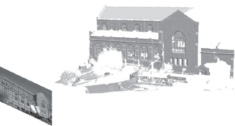
Figure 8.32.
Frequently, a LiDAR scanner is augmented with an RGB camera image calibrated
to be in the same coordinate system.
higher resolution than the laser scan, so it's more accurate to say that we knowwhere
the image plane is in the scanner's coordinate system, as illustrated in Figure
8.32
.
This additional color and texture information allows us to leverage the techniques
described in Chapter
4
to create feature detectors and descriptors better suited to
large, complex scenes.
One effective approach, as proposed by Smith et al. [
460
], is to detect DoG fea-
tures in the co-registered RGB images as described in Section
4.1.4
. Next, each
detected feature location can be backprojected from the scanner's perspective into
the scene, until the ray penetrates the scan mesh, as illustrated in Figure
8.33
.
A square planar patch is constructed in 3D whose normal agrees with the nor-
mal at the backprojected point and whose orientation is defined with respect to
the dominant gradient of the image feature (Section
4.2.1
). A 4
4 grid superim-
posed on this 3D patch is reprojected onto the image plane, and these non-square
bins are used to construct a SIFT descriptor (Section
4.2.3
). The advantage of these
back-projected SIFT features
is that they exploit both image and range information
×