Graphics Reference
In-Depth Information
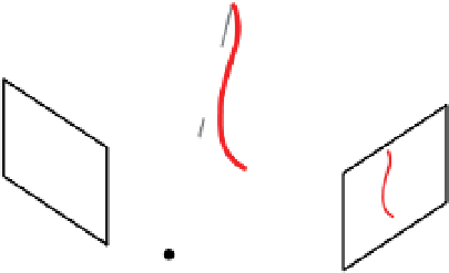
Camera
Camera
Laser
(a)
(b)
Figure 8.13.
(a) A 3D acquisition rig containing two calibrated cameras (left and right) and a
structured light projector (center). (b) The intersection of the laser stripe's projection and an
epipolar line in the left image plane generates a unique correspondence in the right image plane,
which can be triangulated to determine a 3D point on the object's surface.
Precise calibration of such laser-stripe systems is critical; vendors of commercial
systems usuallyoffer preciselymachinedcalibrationobjects of knowngeometry toaid
in recalibration. An easier approach that doesn't require precise calibration between
the image and light planes is to use two rigidly mounted cameras (i.e., a stereo rig),
as illustrated in Figure
8.13
a. In this case, we first calibrate the stereo rig as described
in Section
6.4
. Then an uncalibrated, roughly vertical laser stripe is swept across the
surface. Each position of the stripe results in a pair of images from the two cameras.
The intersection of the stripe with each pair of conjugate epipolar lines produces
an image correspondence. Since the stereo rig is calibrated, the rays through each
pair of corresponding points can be triangulated to obtain a 3D point, as illustrated
in Figure
8.13
b. In this case, the laser stripe simply provides a way to obtain an
unambiguous correspondence along each pair of conjugate epipolar lines.
8
In the previous discussion, we assumed that the center of the laser stripe could
be accurately determined in the camera image (for example, by fitting a Gaussian
distribution to the stripe's profile and finding the peak). However, this approach can
be problematic when the stripe hits a corner in the scene or straddles a reflectance
discontinuity on the object. Curless and Levoy [
111
] showed that the triangulation
could be made even more precise using
space-time analysis
— that is, by observing
the evolution of the stripe's image as it moves across the object. Figure
8.14
illustrates
the idea; as the stripe passes across the indicated point on the object, the returned
laser intensity at the camera rises, then falls. By finding the peak of a Gaussian func-
tion fit to this space-time curve, the exact time at which the stripe hits the point can
be estimated.
Finally, we note that much computer vision research uses an LCDor DLP projector
to create stripes and patterns instead of a laser. In this case, the calibration process is
very similar to the plane-based camera calibrationmethod described in Section
6.3.2
.
First we calibrate the camera as usual by showing it several images of a moving
checkerboard. The projector can also be thought of as a camera that always “sees”
8
Davis and Chen [
113
] describe how a single camera and a system of mirrors can be used to avoid
the need for a second camera.