Graphics Reference
In-Depth Information
Combining Equation (
8.1
) with Equation (
8.2
) yields the key phase-based equation
c
2
d
=
(8.3)
ω
, this introduces a
constraint on the maximum range that can be measured before introducing
range
ambiguity
. That is, we require that 0
Since the phase difference can only be measured modulo 2
π
, which in practice imposes amaximum
other hand, phase-based systems are quite a bit faster than pulse-based systems, a
great advantage when time is of the essence.
<ψ<
2
π
8.1.3
Flash LiDAR
Flash LiDAR
is the name given to a technology used for obtaining low-resolution,
close-range depth maps in real time. However, the name is a bit confusing since
there's no laser that scans across the scene point by point. Instead, the scene is
bathed in spatially uniform, temporallymodulated infrared light, and a CMOS sensor
computes depth measurements over all the pixels of a small (e.g., 176
144) array
simultaneously. Such devices are also called
time-of-flight cameras
. This name is
also somewhat confusing, since pulse-based LiDAR directly (and more accurately)
measures time of flight to compute distances. Figure
8.8
depicts a flash LiDAR device.
Flash LiDAR data acquisition uses the same principles as the LiDAR technologies
discussed earlier. Some systems use a pulse (often the pulses are a bit wider than
×
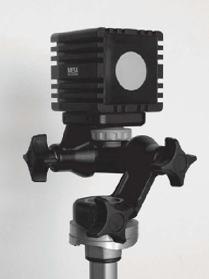
Figure 8.8.
A flash LiDAR device, also
known as a time-of-flight camera. The CMOS
sensor in the middle (the silver circle) is sur-
rounded by a bank of infrared LEDs that
illuminate the scene.
6
It's possible to design algorithms to resolve this ambiguity using phase unwrapping techniques, if
we put constraints on the extent or spatial gradient of objects in the scene. Alternately, multiple
modulating frequencies can be used with the downside of increasing scanning time.