Graphics Reference
In-Depth Information
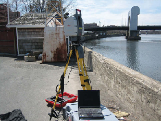
(a)
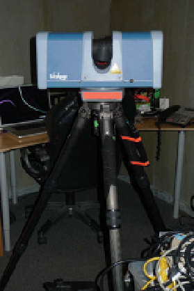
(b)
Figure 8.1.
(a) A time-of-flight-based LiDAR scanner. (b) A phase-based LiDAR scanner.
d
φ
θ
LiDAR
Figure 8.2.
The principle of LiDAR scanning.
scanners were mounted in airplanes and used to generate high-quality terrain maps
for military and geospatial applications.
Figure
8.3
illustrates an example LiDAR scan of a large building. We can appreciate
the millimeter accuracy of the scan, even though the scanner was approximately
fifty meters away from the sixty-meter-wide building. Since the scanner's laser can't
penetrate solid objects, LiDAR scans have characteristic “shadows” of missing data
produced by occluding foreground objects, which can be seen in Figure
8.3
a. These
shadows can be filled in with data from scans from different perspectives once they
have been registered to a common coordinate system, as described in Section
8.4.2
.
While the 3D data acquired from a LiDAR scanner is generally of very high quality,
it's important to note that somematerials are problematic for laser-ranging technolo-
gies. Highly reflective surfaces such as glass generally result in missing or incorrect
distance measurements, since the laser beam can easily bounce off the object and
hit another surface in the scene. Depending on the type of glass, the laser beammay