Graphics Reference
In-Depth Information
separate passes for live action, dangerous elements, lighting, models and minia-
to create the final shot, as discussed in Chapters
2
and
3
.
While motion control rigs are highly precise, they are also extremely large and
expensive. In this section, we generalize optical flow techniques to achieve a motion-
control effect in situations where it would be infeasible to use a professional rig.
We call this problem
video matching
. Formally, we consider two video sequences
I
1
. The problem is to estimate a flow field and time offset at each
frame according to a generalized brightness constancy assumption:
(
x
,
y
,
t
)
and
I
2
(
x
,
y
,
t
)
I
2
(
x
+
u
,
y
+
v
,
t
+
δ)
=
I
1
(
x
,
y
,
t
)
(5.58)
Caspi and Irani [
84
] addressed a simplified version of the videomatching problem
for a rigidlymounted pair of cameras, assuming the two video sequences were related
by a spatial projective transformation and a constant temporal offset. Sand and Teller
[
420
] addressed the more general video matching problem, illustrated in Figure
5.19
;
we summarize the approach here.
Consider a candidate pair of images, one from each video sequence. We estimate
a set of feature matches between the pair, for example, by detecting and matching
Harris corners. Each match is assigned a confidence based on the similarity of the
local neighborhoods around the pair of feature locations. These confidence-weighted
feature matches are used to build a dense correspondence field between the image
pair, using a locally weighted regression to estimate a smooth optical flow field. The
input and the output of the algorithmare the same as the scattered data interpolation
methods described in Section
5.2
; like these methods, the resulting dense correspon-
dence field cannot represent discontinuities. By comparing the actual second image
with the warped first image predicted by the motion field, we identify regions of
(a)
(b)
(c)
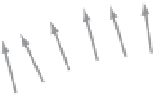
Figure 5.19.
The video matching problem. We begin with two video sequences (a) and (b) that
follow roughly the same trajectory in space (curved line). The arrows indicate viewpoints at
equally spaced points in time, showing that the video sequences have different fields of view and
velocities. After video matching in (c), frames of the second sequence are aligned both spatially
and temporally with the first sequence, for subsequent use in applications like compositing.
20
For models and miniatures, the camera motion and software must compensate for the different
scale with respect to live action. For more information on motion control, see Rickitt [
393
].