Database Reference
In-Depth Information
Step 1: Shift right with incoming bit set to 1
Incoming bit
Shift
Outgoing bit
0010110100
1001011010
0100101101
0010010110
0010010110
1
→
→
→
0
0
1
Loop: While the outgoing bit is zero
shift right with incoming bit set to 0
Shift
0
(a)
(b)
Figure 9.6
(a) Diagram of the algorithm for index remapping from Z-order
to the hierarchical out-of-core binary tree order. (b) Example of the sequence
of shift operations necessary to remap an index. The top element is the original
index and the bottom is the remapped, output index.
Figure 9.7 shows the data layout obtained for a 2D matrix when its ele-
ments are reordered following the index
I
. The data is stored in this order
and divided into blocks of constant size. The 2D image of such decomposition
has the first block corresponding to the coarsest level of resolution of the data.
The subsequent blocks correspond to finer and finer resolution data, which is
distributed more and more locally.
B0
B1
B2
B3
B4
B5
B6
B7 B8
B9 B10 B11
B0
B4
B8
B1
B5
B9
B2
B6
B10
B3
B7
B11
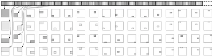
Figure 9.7
Data layout obtained for a 2D matrix reorganized using the in-
dex
I
(1D array at the top). The 2D image of each block in the decomposition
of the 1D array is shown. Each gray region (odd blocks dark gray, even blocks
light gray) shows where the block of data is distributed in the 2D array. In
particular the first block is the set of coarsest levels of the data distributed
uniformly on the 2D array. The next block is the next level of resolution
still covering the entire matrix. The next two levels are finer data covering
each half of the array. The subsequent blocks represent finer resolution data
distributed with increasing locality in the 2D array.