Geoscience Reference
In-Depth Information
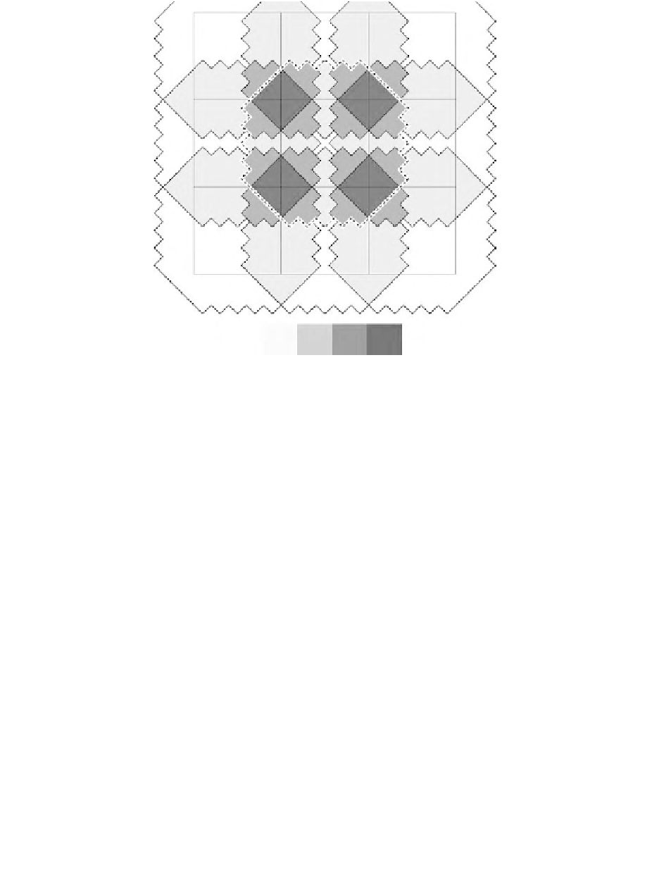
1 2 3 4
Number of Overlapping Smooth Pixels
Figure 20.4
Scaled model of a three-by-three block of smoothed OLS PMT pixels. The dashed line indicates
the boundary of a single smoothed pixel IFOV at the nadir, as modeled in Figure 20.3. Because
of the substantial overlap between adjacent smoothed pixel IFOVs it is possible for point sources
of light to show up in more than one smoothed pixel. The number of overlapping smoothed OLS
pixel IFOVs for each polygon is indicated using the grayscale. Additional levels of overlap are
encountered in actual OLS imagery as the pattern is extended beyond this three-by-three example
and as the IFOV expands at off-nadir scan angle conditions.
scan line. The geolocation algorithm calculates the position of each OLS pixel center using the
satellite ephemeris, a calculation of the scan angle, an earth geode model, and a terrain correction
using GTOPO30. The pixel center positions were used to locate the corresponding 30 arc second
grid cells, which are filled with the OLS DN values. This generates a sparse grid, having DN data
only in cells containing OLS pixel centers. The complete 30 arc second grids were then filled to
form a continuous image using nearest-neighbor resampling of the sparse grids.
20.2.3
Target Selection and Measurement
A composite of cloud-free light detections was produced using data from the entire time series.
The composite values indicated the number of times lights were detected for each 30 arc second
grid cell. These were then filtered to remove single-pixel light detections, a set that contains most
of the system noise (Figure 20.5). The cloud-free composites were then used to identify persistent
light sources (present through the entire time series) for potential use in the study. Two types of
persistent lights were selected: (1) isolated point sources with lighting ground areas much smaller
than the OLS pixel, such as oil and gas platforms in the Santa Barbara Channel (Figure 20.6) and
(2) isolated lights with more extensive areas of ground lighting. We identified five point sources:
four oil and gas platforms (Channel Islands 1-3 and Gaviota 1) and a solitary light present at an
airfield on San Nicolas Island. Calibration targets with more extensive area of lighting included a
series of cities, towns, and facilities found on land (Table 20.1).