Graphics Reference
In-Depth Information
22. Connect the Color output of the Image Texture_Name node to the Color2 input
socket of the Mix_Hull_Name node. Then connect the Alpha output of the Image
Texture_Name node to the Fac input socket of the Mix_Hull_Name node.
23. Go to the Mapping4_Name node and check both the Min and Max items. Then
set the Location value of X to
-3.300
and Y to
1.000
. Set the Scale value of Y to
2.500
. (These values depend on the scale and location you want for your logo on
the spaceship; just experiment looking at the real-time-rendered preview.)
24. Add a Frame (press
Shift
+
A
and navigate to Layout | Frame). Press
Shift
and
select the Mapping4_Name node, the Image Texture3_Name node, and
then the Frame. Press
Ctrl
+
P
to parent them. Label the frame as
NAME
, as
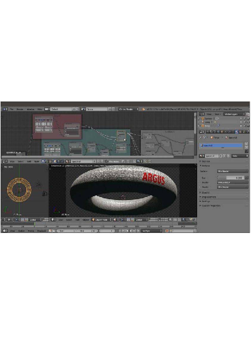
shown in the following screenshot:
The ARGUS logo on the hull
The steps to create the windows are as follows:
25. Add a new Mapping node (press
Shift
+
A
and navigate to Vector | Mapping) and
two Image Texture nodes (press
Shift
+
A
and navigate to Texture | Image Texture).
Label them as
Mapping5_Windows
,
Image Texture4_Windows
, and
Image
Texture5_Windows
. Connect the Texture Coordinate node's UV output and the
Mapping node's output to the Image Texture nodes as usual. Then set the
Mapping node's Scale values to
10.000
for the three axes.
26. Click on the Open button of the Image Texture4_Windows node and load the
spacehull_windows_lights.png
image. Then click on the Open button
of the Image Texture5_Windows node and load the
spacehull_windows_bump.
png
image. Set Color Space for both the image nodes to Non-Color Data.