Geoscience Reference
In-Depth Information
Azimuth
Y'
Proportional
Y
Erosion
Truncation
Dip
Onlap
X'
y°
X
x°
Erosion
Combination
Z
Fig. 3.15
Translation of a (X
0
;Y
0
) origin to (X';Y')
Fig. 3.16
Examples of different correlation styles. (Deutsch
2002
)
mentary strata-bound deposits where the mineralization
has continuity along the stratigraphic unit of interest. The
strata may be folded (plastic) or fractured with little lat-
eral displacements of the units, such that it appears to be
continuous. Then, the original Cartesian coordinates X, Y, Z
are transformed into a Stratigraphic or Unfolded Coordinate
Systems (SCS or UCS). All calculations being carried out in
the SCS and then back-transformed to real-world Cartesian
coordinates. Examples and details of this type of transforma-
tion are shown in David (
1988
); Dagbert et al. (
1984
); Sides
(
1987
), or Deutsch (
2005
).
Modeling 2-D stratigraphic or multiple layered deposits
often requires the vertical coordinate to be transformed to a
stratigraphic coordinate. Figure
3.16
shows schematic illus-
trations of different basic correlation types for stratigraphic
layers. Each layer is modeled independently with a relative
stratigraphic coordinate
z
rel
derived from four surface grids:
Converting all depth measurements to
z
rel
permits modeling
of each stratigraphic layer in regular Cartesian
X, Y, Z
rel
co-
ordinates. The locations of all data (geologic variables and
grades) are converted back to real
Z
coordinates before visu-
alization, volumetric calculations, or planning calculations.
There will be no back-transformed
z
values outside the exist-
ing interval
z
∉
(z
et
, z
eb
)
because these locations are known
ahead of time and excluded from modeling.
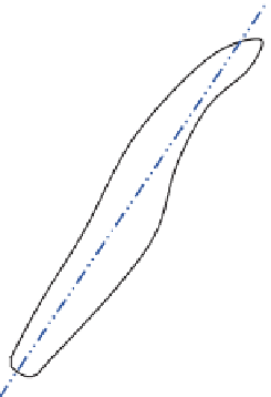
Another transformation could be considered in cases
where there is large scale undulation or curvature. There are
many variants used of this type of transformation commonly
called unfolding. One procedure is to transform the X coor-
dinate to be the distance from an arbitrary center line Y co-
ordinate, which is along the primary direction of continuity
and is left unchanged, see Fig.
3.17
:
zz
−
cb
z
=
⋅
T
rel
z
−
z
xxfy
=−
c
()
ct
cb
where
f
c
(y)
is the deviation of the undulating centerline from
a straight constant
X
reference line.
Straightforward normal faults can be handled by correla-
tion grids and stratigraphic coordinate transformation. Re-
verse faults cause problems because there are multiple sur-
face values at same x, y locations, see Figs.
3.18a
and
b
. The
grid can be expanded to avoid overlap. Specialized software
is used for more complex gridding schemes.
where the cb refers to the correlation base and ct refers to
the correlation top. The
T
parameter is the average thickness
of the layer under consideration. The relative stratigraphic
coordinate is 0° at the base and
T
at the top.
This transform may be reversed by
z
rel
zz
=+⋅ −
(
Z Z
)
cb
ct
cb
T