Geoscience Reference
In-Depth Information
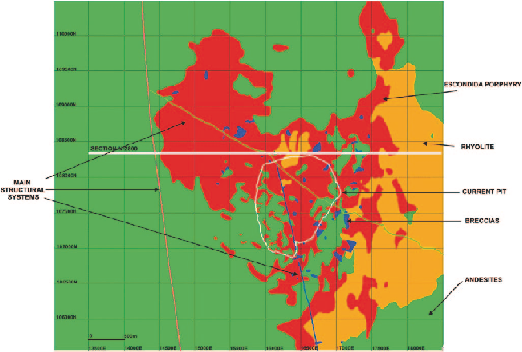
Fig. 3.2
Plan view of the Escondida Lithology model, October 2001, Bench 2800. Note the position of Section N104800, shown in Fig.
3.3
The drawn geological shapes should be based on a suf-
ficient amount of drill hole information and other geologic
knowledge that could include a model for ore deposition,
surface mapping, and structural and radiometric informa-
tion. Surfaces are sometimes referred to as Digital Terrain
Models (DTM), while wireframes are used to define three-
dimensional volumes corresponding to a geologic variable.
An alternative to wireframes is to simply extrude or extend
the two-dimensional polygonal shapes a fixed distance to ei-
ther side of the plan of interpretation. Although simpler and
quicker, this option often results in an overly simplistic and
sometimes inconsistent model.
The shapes should be drawn with a degree of confidence
related to the data density. If continuity cannot be established
between sections, then the confidence in the interpretation
will be poor. The required drill hole spacing for adequate in-
terpretation is related to the mineralization type. A small vein
type deposit may have drill hole information spaced 20 m or
less, while a massive bulk tonnage deposit may have drill
holes spaced 50, 70, or more meters apart. In either case, the
geological variable being modeled should be continuous for
two or three sections of drill hole spacing units, implying a
reasonable degree of confidence in continuity. However, al-
though it should never become part of the published, official
resources, it is sometimes necessary to allow for extrapola-
tion of geologic features to aid in future exploration.
Rules about extrapolating at depth or laterally past the last
points of information should be clearly stated. A safe option
is to avoid excessive extrapolation by creating an outer enve-
lope around the drill hole information to constrain interpreta-
tion and modeling.
Drill hole data and a plan view of drill hole locations pro-
vide a starting point for geological interpretation. Sections
are chosen based on the drill hole distribution. Multiple sec-
tions are combined to form a 3-D model that is consistent
with information from all sections.
The simplest methods used to obtain models of geologic
attributes are based on two-dimensional interpretation, gen-
erally done on cross sections. Then, the resulting polygons
representing the interpreted shapes are refined on a second
set of longitudinal sections. Finally, the model can be refined
on plan views. This was done for the lithology model shown
in Figs.
3.2
and
3.3
.
The order of two-dimensional interpretation depends on
the geometry of the deposit. For open-pit, disseminated-type
deposits, the final stage should be plan views, because the