Geoscience Reference
In-Depth Information
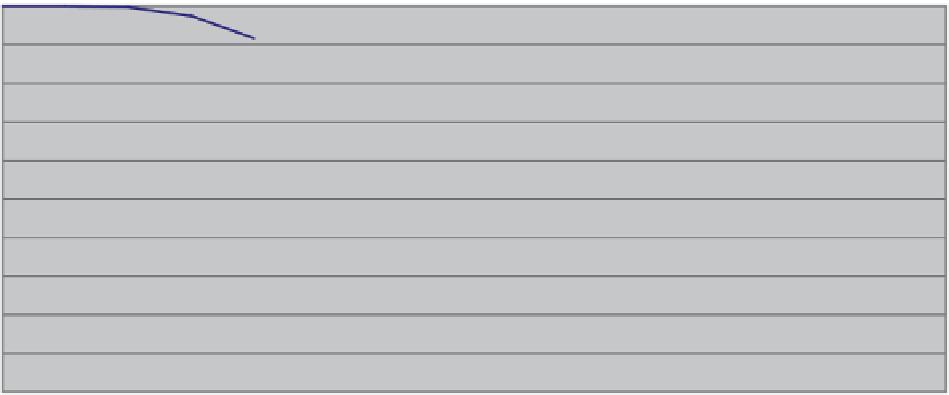
3UHGLFWHG*UDGH7RQQDJH&XUYH
*82[LGHV
&XWRII*UDGH
7RQV608!FR
7RQV&RPSV!FR
*UDGH608!FR
*UDGH&RPSV!FR
Fig. 14.21
Predicted Grade-Tonnage curve, 10 m declustered composites vs. SMU (from the DG model), TCu, Domain 1 (Oxides)
a relative loss in grade of about 6 % (from 1.104 % TCu to
1.045 % TCu), and a gain of about 0.5 % in tons.
manner, geologic contact dilution is incorporated into the
resource model.
14.1.21
The Cerro Colorado 2003 Resource
Block Model
14.1.22
The Grade Model
Ordinary Kriging (Chap. 8) was used to estimate the grade
for each Domain, using the corresponding correlogram mod-
els and applying kriging plans and criteria derived from the
statistical analyses described above.
The kriging process was implemented in three estimation
passes, each with varying restrictions in the kriging plan. In
the more restrictive pass (Pass 1), shorter search radii were
used along with a relatively large minimum number of com-
posites; the second and third passes progressively relax these
conditions, although in all cases a minimum of two drill holes
is required for any block to be estimated. The purpose of these
passes is to (a) estimate the blocks that are well informed with
more local information, while the opposite is true for blocks
in outer areas of the deposit. This results in a block model dis-
tribution with higher variance than otherwise, and thus pro-
vides better control over the smoothing effect of kriging; and
(b) to provide an initial indicator for resource classification,
since the kriging plan provides the summary of all parameters
required to estimate each block, and it is domain-specific,
which implies that the local geology is taken into consid-
eration. This is accomplished by storing a flag in the block
model indicating in which pass the block was estimated.
The kriging plans were the result of a calibration or cross
validation exercise using production date. The existing blast
The resource block model defined is 3,600 m long in the
East-West direction, 2,200 m long in the North-South direc-
tion, and 710 m deep. A limiting lower surface was devel-
oped based on current drill hole depth, extending on cross
sections the end points of drill holes between 20 and 30 m.
This lower surface ensures that all drill holes are contained
within the model, and also avoids undue extrapolation of
drill hole grades at depth. A block size of 20 × 20 × 10 m was
deemed appropriate for the available drill hole spacing. Ac-
cording to Journel and Huijbregts (
1978
), block size should
correspond to approximately 1/3 to 1/2 of the average drill
hole spacing, which is about 50 × 50 m after infill drilling is
completed.
To incorporate geologic contact dilution, a partial block
definition was implemented. An auxiliary variable-block
size model was first defined, and geologic attributes as-
signed to each block in this auxiliary model. Then, the vari-
able-block size model was re-blocked to the 20 × 20 × 10 m
block model defined above, and percentages of Domains
were calculated for each large block. Thus, a detailed defi-
nition of the local geologic contacts is obtained, with the
final grade of the block estimated based on a weighted
average of the estimated grades for each Domain. In this