Environmental Engineering Reference
In-Depth Information
500 S/s
2 s/div
CH1
CH2
20.00 V
8.00 V
Main: 10 k
CH1
5.00
DC
CH2
2.00
DC
100:1
V/div
Full
100:1
V/div
Full
Expanded
View
-8.00 V
-20.00 V
-10.000 s
10.000 s
50 ms/div
(a) Output Voltage of Power Storage and Supply
Circuit
Edge CH1
AutoLevel
20.00 V
(a) Output Voltage
of Linear Regulator
-8.00 V
-20.00 V
5.250 s
5.750 s
P-P
Max
Min
Avg
(C1)
(C1)
(C1)
(C1)
4.16667 V
8.75000 V
4.58333 V
7.23005 V
P-P
Max
Min
(C2)
(C2)
(C2)
4.16667 V
4.00000 V
-166.667 mV
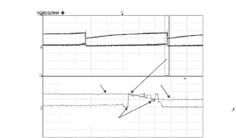
FIGURE 2.44
Waveforms of (a) a charging and discharging of the output voltage of energy storage and supply
circuit and (b) the output voltage of voltage regulator.
station in a wireless manner. Referring to
Figure 2.44
, it can be seen that the
output voltage of the harvester takes about 10 s to charge the storage capacitor
to maximum voltage
V
ma x
of around 8.8 V. As soon as the capacitor reaches
V
ma x
, the electrical energy stored in the capacitor is discharged to the RF load,
and the voltage across the capacitor starts to decrease to the minimum voltage
V
mi n
of 4.58 V in 100 ms. After this, the cycle starts again.
To find the amount of energy that has been stored in the storage capacitor
during the time when the capacitor is charged from
V
min
to
V
max
,
Equation 2.33
is applied. The energy stored in the capacitor is calculated to be
917
J.
2
C
V
max
−
V
min
1
E
cap
=
(2.33)
The electrical power consumed by the RF transmitter load is dependent on
the number of digital-encoded data word being transmitted. For each data
word, the time taken for one transmission is 20 ms, that is, 10 ms of active
time and 10 ms of idle time. During the active transmission time, the RF load
requires a supply voltage and current of 3.3 V and 4 mA, respectively, to oper-
ate. As for the remaining time of 10 ms, the RF load is operating in idle mode,


Search WWH ::

Custom Search