Environmental Engineering Reference
In-Depth Information
.50
(12.7)
W
θ
Z
Z
(Yaw)
Piezoelectric
Wind
Harvester
θ
Z
L
(Pitch)
θ
Z
W
(Roll)
L
Rotation Axes of Piezoelectric Wind
Harvester
θ
Z
#2-56 Clr.
2 plcs.
.25
(6.4)
θ
Z
θ
W
W
θ
.312
(7.9)
Z
Wind Flow
Direction
Piezoelectric Wind
Harvester
Wind Flow
Direction
Wires, 6" (152)
Variation of θ
Z
Variation of θ
W
Wind Flow
Direction
θ
1.0
(25.4)
L
.085
(2.2)
=
2.52
(64.0)
L
Blade
Swing
3.02
(76.7)
Variation of θ
L
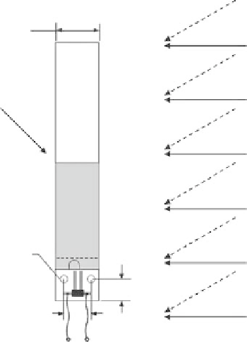
FIGURE 2.36
Orientations and rotating angles of the vibration-based piezoelectric wind energy harvester.
Therefore, experimental results are provided only for rotating angles rang-
ing from 0
◦
to 90
◦
.From the three figures, one common phenomenon that
can be observed: As the rotating angle increases from 0
◦
to 90
◦
, the amount
of electrical power generated by the piezoelectric wind energy harvester de-
creases. This phenomenon is due to the reduction in the net lift force cre-
ated by the pressure difference between the top and bottom surfaces of the


Search WWH ::

Custom Search